
High‑Pressure Burner Design
High‑Pressure Burner Design involves a specialized set of terms that students must master in order to understand the complex interplay of fluid dynamics, thermochemistry, and material science that governs modern combustion systems. The foll…
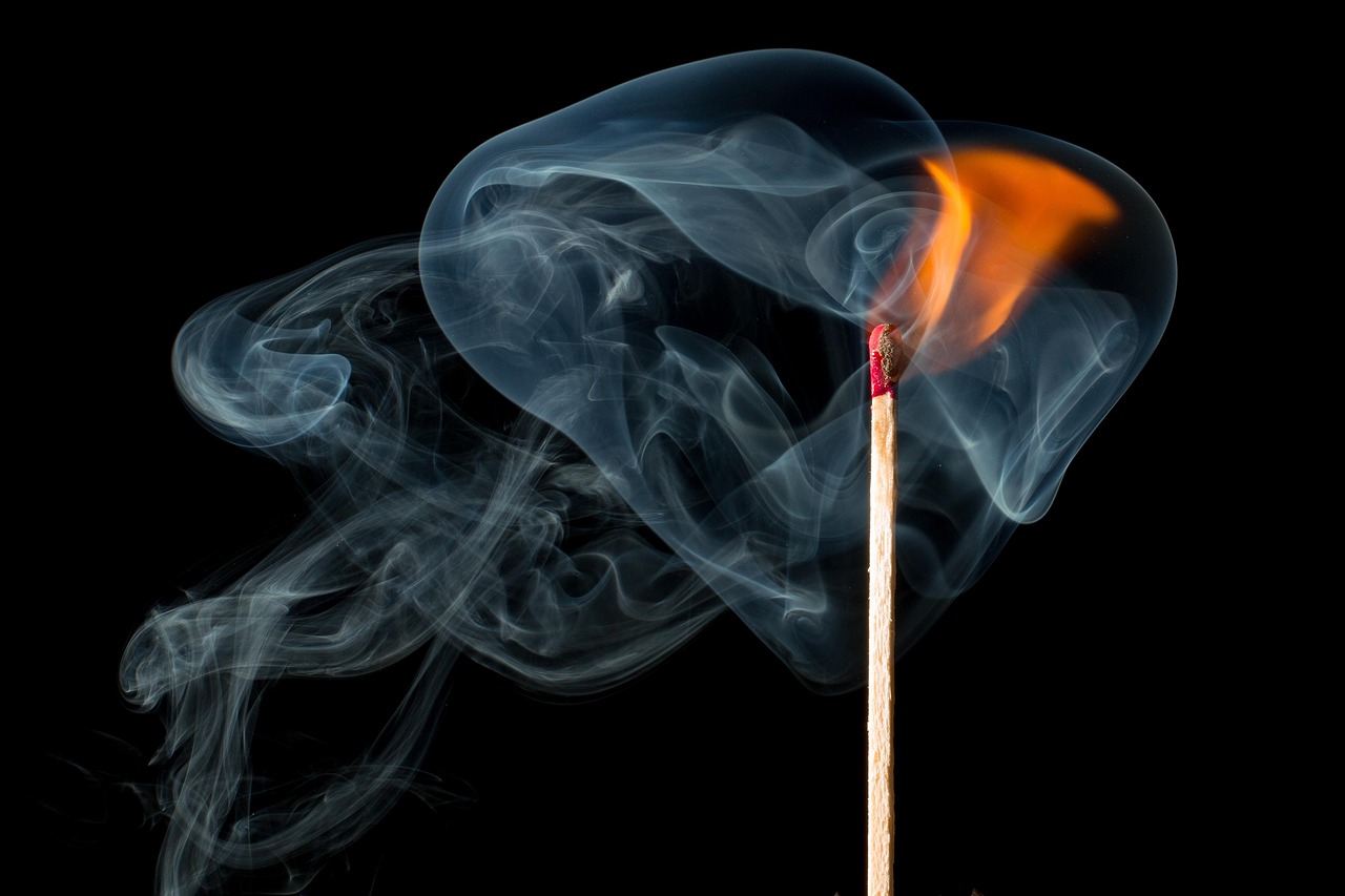
High‑Pressure Burner Design involves a specialized set of terms that students must master in order to understand the complex interplay of fluid dynamics, thermochemistry, and material science that governs modern combustion systems. The following glossary presents each key term with a clear definition, typical values, practical examples, and common challenges encountered in design and operation. The emphasis is placed on concepts that directly influence performance, safety, and emissions compliance in high‑pressure environments such as gas turbines, industrial furnaces, and rocket propulsion units.
Stoichiometric Mixture – The exact proportion of fuel and oxidizer that reacts completely without excess of either component. For a hydrocarbon fuel CxHy, the stoichiometric air‑fuel ratio (AFR) can be calculated from the balanced combustion equation. In a methane‑air system the stoichiometric AFR is approximately 17.2 Kg air per kg fuel. Operating at the stoichiometric point yields the highest flame temperature, typically around 2 200 K for methane, but also maximizes NOx formation. Designers often lean the mixture (lower AFR) to reduce peak temperature and emissions, while maintaining sufficient flame stability.
Equivalence Ratio (Φ) – A dimensionless number that expresses the actual fuel‑to‑oxidizer ratio relative to the stoichiometric ratio. Φ = 1 denotes stoichiometric combustion, Φ < 1 indicates a lean mixture, and Φ > 1 a rich mixture. In high‑pressure burners, a typical operating range is 0.6 ≤ Φ ≤ 0.9 For low‑NOx applications. Adjusting Φ influences flame speed, flame temperature, and pollutant formation. For example, a Φ of 0.8 In a natural‑gas burner reduces flame temperature by roughly 150 K compared with stoichiometric operation, thereby lowering thermal NOx.
Flame Speed – The rate at which the flame front propagates through the unburned mixture. Two distinct forms are relevant: Laminar flame speed (S_L) and turbulent flame speed (S_T). S_L for methane‑air at atmospheric pressure is about 0.38 M s⁻¹; however, at 10 bar the laminar speed drops to roughly 0.25 M s⁻¹ due to increased density. Turbulent flame speed scales with turbulence intensity and is typically several times larger than S_L, often expressed as S_T ≈ u′ · I, where u′ is the RMS turbulence velocity and I is the turbulent‑flame‑speed enhancement factor. Accurate prediction of S_T is critical for ensuring that the flame remains anchored within the burner cavity under high‑pressure conditions.
Residence Time – The average duration that a fluid element spends in the combustion zone. It is calculated as τ = V/Q, where V is the volume of the combustion chamber and Q is the volumetric flow rate. In high‑pressure burners, residence times are short, often on the order of 10–30 ms, because the high flow velocities are required to sustain combustion at elevated pressures. Insufficient residence time can lead to incomplete combustion, while excessive residence time may increase heat loss and promote unwanted side reactions.
Swirl Number (S) – A dimensionless parameter that quantifies the strength of the rotational flow introduced by a swirler. It is defined as S = G_θ/(G_x · R), where G_θ is the axial flux of angular momentum, G_x is the axial momentum flux, and R is the characteristic radius of the swirler. Typical swirl numbers for stable premixed burners range from 0.5 To 1.2. Higher swirl numbers enhance mixing and flame stabilization but also increase pressure drop and can lead to vortex breakdown, which may cause flame blow‑out at very high pressures.
Turbulence Intensity (Tu) – The ratio of the RMS turbulent velocity fluctuations (u′) to the mean flow velocity (U). Tu = u′/U and is expressed as a percentage. In high‑pressure burners, a turbulence intensity of 10–15 % is often targeted to accelerate mixing while avoiding excessive pressure losses. Turbulence intensity directly affects the turbulent flame speed and, consequently, the flame anchoring location.
Flame Stabilizer – A device or geometric feature that creates a low‑velocity recirculation zone to anchor the flame. Common stabilizers include bluff bodies, cavities, and swirl‑induced vortex cores. The stabilizer must be designed to survive high thermal loads (up to 2 500 K) and pressure fluctuations. For example, a cylindrical bluff body of diameter 20 mm placed at the burner throat can generate a stable recirculation zone that holds the flame even at 30 bar inlet pressure.
Pilot Flame – A small, continuously burning flame used to ignite the main combustion zone. Pilot flames are often fueled by a richer mixture to ensure reliable ignition under varying operating conditions. In high‑pressure systems, the pilot flame may be located upstream of the main fuel injection point and must be thermally protected to prevent overheating. An example is a pilot flame operating at Φ = 1.2 With a flow rate of 0.5 Kg h⁻¹, providing a stable ignition source for the primary flame.
Premixed Burner – A burner where fuel and oxidizer are mixed before entering the combustion zone. Premixed operation yields a uniform mixture, leading to lower peak temperatures and reduced NOx. However, premixed burners are susceptible to flashback, where the flame propagates upstream into the mixing section. High‑pressure premixed burners often employ flame arrestors and staged mixing to mitigate flashback risk.
Diffusion Burner – A burner where fuel and oxidizer meet and mix only at the flame front. Diffusion flames are generally more tolerant of mixture variations and are less prone to flashback, but they produce higher peak temperatures and consequently higher NOx. In high‑pressure applications, diffusion burners may be used when fuel flexibility is required, such as in multi‑fuel gas turbines.
Flashback – The undesirable phenomenon where the flame propagates upstream into the premixing region, potentially causing damage to equipment. Flashback risk increases with higher equivalence ratios, lower inlet pressures, and higher flame speeds. Design strategies to prevent flashback include using flame‑holding devices, limiting the maximum inlet temperature, and incorporating diluents such as CO₂ or N₂.
Blow‑out – The opposite of flashback; a flame is extinguished because the flow velocity exceeds the flame’s ability to propagate upstream. Blow‑out occurs when the local flame speed falls below the convective velocity, often due to excessive turbulence, high inlet temperature, or insufficient fuel supply. High‑pressure burners must balance the flow velocity to avoid blow‑out while maintaining efficient mixing.
Quenching Distance – The minimum distance between two solid surfaces that can extinguish a flame. It is a function of mixture composition, pressure, and temperature. For methane‑air at 10 bar, the quenching distance is approximately 0.6 Mm. Burner designs must ensure that gaps larger than the quenching distance are avoided in regions where flame stabilization is required, or else the flame may be unintentionally extinguished.
Heat Transfer Coefficient (h) – A parameter that quantifies the rate of heat exchange between the flame and surrounding surfaces. In high‑pressure burners, convective heat transfer dominates, and h can range from 200 to 1 000 W m⁻² K⁻¹ depending on flow velocity and turbulence. Accurate estimation of h is essential for thermal‑stress analysis of burner components.
Radiation Heat Loss – The portion of heat transferred from the flame to surrounding surfaces via electromagnetic radiation. At high flame temperatures, radiation can account for up to 30 % of total heat loss. Radiative heat flux is proportional to ε σ T⁴, where ε is the emissivity, σ is the Stefan‑Boltzmann constant, and T is the absolute temperature. Materials with high emissivity (e.G., Ceramic coatings) are often used to enhance radiative cooling of burner walls.
Conduction Losses – Heat transferred through solid materials, such as burner walls and support structures. In high‑pressure burners, conduction losses are minimized by using low‑thermal‑conductivity alloys (e.G., Inconel 718) and by incorporating thermal insulation layers. Conduction analysis typically involves solving Fourier’s law in one‑dimensional or multi‑dimensional configurations.
Nozzle Design – The geometry that shapes the flow of fuel and oxidizer into the combustion chamber. Nozzle parameters include throat diameter, convergent‑divergent profile, and exit angle. In high‑pressure burners, the nozzle must withstand pressure ratios up to 5:1 While maintaining uniform velocity distribution. A well‑designed convergent nozzle can reduce pressure drop by 10–15 % compared with a simple orifice.
Orifice Sizing – Determination of the hole diameter that controls mass flow rate. The orifice equation Q = C_d A √(2 ΔP/ρ) relates flow rate Q to discharge coefficient C_d, area A, pressure drop ΔP, and fluid density ρ. For a methane flow at 20 bar with a desired mass flow of 0.5 Kg s⁻¹, an orifice diameter of roughly 4 mm may be required, assuming C_d ≈ 0.8.
Fuel Atomization – The process of breaking liquid fuel into fine droplets to promote rapid vaporization and mixing. Atomization quality is characterized by the Sauter mean diameter (SMD). At high pressures, SMD values of 20–40 µm are typical for gas‑oil mixtures. Smaller droplets increase surface area, reducing vaporization time and improving combustion efficiency.
Droplet Size Distribution – The statistical spread of droplet diameters within an atomized spray. It is often described by a Rosin‑Rammler or log‑normal distribution. In high‑pressure burners, controlling the distribution is critical because large droplets can lead to incomplete combustion and high soot formation. Spray nozzles with multi‑hole designs can achieve narrower distributions.
Injector Design – The arrangement of fuel and air injection ports to achieve optimal mixing. Injectors may be coaxial, annular, or multi‑jet. For high‑pressure gas turbines, a dual‑stage injector with a primary premixed stage followed by a secondary diffusion stage can provide stable operation across a wide load range. Design considerations include pressure drop, spray pattern, and susceptibility to fouling.
Mixing Length – The characteristic distance over which fuel and oxidizer achieve a homogeneous mixture. In turbulent flows, the mixing length L_m can be approximated by L_m ≈ u′ · τ, where τ is the turbulent eddy turnover time. In a high‑pressure burner with u′ = 30 m s⁻¹ and τ = 0.001 S, L_m is about 30 mm. Adequate mixing length must be accommodated within the burner geometry to avoid local rich or lean pockets.
Reynolds Number (Re) – A dimensionless quantity that indicates the relative importance of inertial forces to viscous forces in a flow. Re = ρ U D/μ, where ρ is density, U is mean velocity, D is characteristic length, and μ is dynamic viscosity. High‑pressure burners typically operate at Re > 10⁴, ensuring fully turbulent flow. However, excessive Re can increase pressure losses and acoustic noise.
Mach Number (Ma) – The ratio of flow velocity to the local speed of sound. In most burners, Ma is kept below 0.3 To avoid compressibility effects. At 20 bar and 300 K, the speed of sound is about 500 m s⁻¹; a flow velocity of 150 m s⁻¹ yields Ma ≈ 0.3. Maintaining subsonic flow simplifies the design of inlet manifolds and prevents shock‑induced flame instabilities.
Specific Heat Capacity (c_p) – The amount of heat required to raise the temperature of a unit mass of a substance by one degree at constant pressure. For air at 300 K, c_p ≈ 1 005 J kg⁻¹ K⁻¹. Accurate values of c_p for fuel‑air mixtures are essential for calculating enthalpy changes and predicting flame temperatures under high‑pressure conditions.
Enthalpy (h) – The total heat content of a flowing fluid, defined as h = u + p/ρ, where u is internal energy, p is pressure, and ρ is density. In combustion analysis, the enthalpy balance across the burner determines the temperature rise of the products. For a methane‑air mixture, the lower heating value (LHV) corresponds to an enthalpy release of about 50 MJ kg⁻¹ fuel.
Entropy (s) – A thermodynamic property that measures the degree of disorder or irreversibility in a system. In high‑pressure burners, entropy generation is associated with mixing, heat transfer, and friction. Minimizing entropy production can improve overall combustion efficiency. Engineers often use the exergy analysis framework, which incorporates entropy, to evaluate performance.
Combustion Kinetics – The set of chemical reactions and rate laws that describe how fuel molecules break down and form products. For methane, the primary chain‑branching steps involve H + O₂ → OH + O and subsequent reactions leading to CO₂ and H₂O. Detailed kinetic mechanisms may contain hundreds of elementary steps; however, reduced mechanisms (e.G., GRI‑3.0) Are commonly employed in CFD simulations of high‑pressure burners.
Reaction Mechanism – A collection of elementary reactions, each with an associated rate constant and activation energy. Accurate mechanisms are required to predict pollutant formation, such as NOx and CO, especially under high‑pressure conditions where third‑body collisions become significant. Mechanisms are often validated against shock‑tube experiments and rapid compression machine data.
Ignition Delay – The time interval between the introduction of a fuel‑oxidizer mixture and the onset of rapid combustion. Ignition delay depends on temperature, pressure, and mixture composition. At 30 bar, methane‑air can ignite within 0.5 Ms at 1 800 K, whereas at 1 bar the same mixture may require 2 ms. Designers must ensure that the burner geometry provides sufficient residence time for ignition, particularly in staged‑combustion schemes.
Autoignition Temperature – The lowest temperature at which a fuel‑oxidizer mixture will ignite spontaneously without an external spark. For methane, the autoignition temperature at 1 atm is about 1 030 K; at 20 bar it drops to roughly 850 K due to increased collision frequency. High‑pressure burners often operate near but below the autoignition temperature to avoid uncontrolled ignition.
Flame Propagation – The movement of the flame front through the unburned mixture. Propagation speed is governed by the balance of chemical heat release and heat diffusion. In high‑pressure environments, the increased density reduces the diffusion rate, slowing flame propagation. However, turbulence can compensate by enhancing mixing, leading to a higher turbulent flame speed.
Flame Front – The thin zone where the chemical reaction occurs, typically a few millimeters thick in laminar flames. In turbulent flames, the front becomes highly wrinkled, increasing its surface area and thus the overall reaction rate. Visualization techniques such as OH‑planar laser-induced fluorescence (OH‑PLIF) are used to study flame front structure in high‑pressure burners.
Flame Holder – A component that creates a low‑velocity zone to anchor the flame, similar to a flame stabilizer but often more compact. Examples include a small recessed cavity or a venturi throat with a step. Flame holders must be designed to survive thermal cycling and pressure pulsations. A common material choice is a high‑temperature alloy with a protective ceramic coating.
Pressure Vessel – The enclosure that contains the high‑pressure combustion gases. Design of the pressure vessel follows ASME Boiler and Pressure Vessel Code Section VIII, which specifies allowable stress values, design temperature, and safety factors. For a burner operating at 30 bar, the vessel wall thickness may be on the order of 10 mm if constructed from Inconel 625, assuming a safety factor of 1.5.
Safety Factor – The ratio of the material’s allowable stress to the maximum anticipated stress. In high‑pressure burner design, a safety factor of 1.5 To 2.0 Is typical for structural components, while a higher factor (up to 3.0) May be required for components exposed to cyclic thermal loads. The safety factor ensures reliability under unexpected transients such as pressure spikes or rapid load changes.
ASME Code – The American Society of Mechanical Engineers standards governing the design, fabrication, and inspection of pressure vessels and piping. Compliance with ASME Section VIII, Division 1 is mandatory for commercial burners. The code prescribes material specifications, allowable stress tables, and testing requirements such as hydrostatic pressure testing.
API Standards – The American Petroleum Institute specifications for equipment used in the oil and gas industry. Relevant standards for burners include API 650 (welded tanks), API 620 (large pressure vessels), and API 560 (flame arrestors). These standards address corrosion resistance, welding procedures, and fire‑safety considerations.
Low‑NOx Burner – A burner designed to minimize thermal NOx formation by controlling flame temperature, residence time, and oxygen concentration. Strategies include staged combustion, flue‑gas recirculation (FGR), and use of water or steam injection. For example, a staged‑combustion burner may first burn a fuel‑lean mixture (Φ ≈ 0.6) To create a hot, low‑oxygen zone, followed by a secondary richer stage (Φ ≈ 0.9) That completes combustion while keeping peak temperatures below 1 800 K.
Staged Combustion – A technique where fuel and oxidizer are introduced in separate zones, allowing the first stage to partially oxidize the fuel under lean conditions. The second stage completes combustion, often at a higher equivalence ratio. Staging reduces NOx because the first stage limits peak temperature, and the second stage benefits from the recirculated hot gases that promote rapid oxidation without raising temperature excessively.
Flue‑Gas Recirculation (FGR) – The process of redirecting a portion of the exhaust gases back into the combustion zone. Recirculated gases increase the specific heat capacity of the mixture, diluting the reactants and lowering flame temperature. In high‑pressure burners, FGR ratios of 10–30 % are common. A practical implementation may involve a bypass line with a control valve that mixes a measured amount of flue gas with fresh air.
Swirl‑Induced Vortex – The rotating flow structure generated by a swirler, which creates a central low‑pressure core and a surrounding high‑velocity annulus. The vortex enhances mixing and provides a natural flame anchoring location. Swirl numbers above 0.6 Typically produce a stable vortex core that can hold the flame even at pressures exceeding 20 bar.
Vortex Breakdown – A phenomenon where the central vortex core collapses, leading to a sudden change in flow pattern and potential flame instability. Vortex breakdown can be triggered by excessive swirl, high Reynolds number, or abrupt changes in geometry. Designers mitigate this risk by smoothing transitions and avoiding abrupt area changes in the swirler section.
Acoustic Instability – Oscillations that arise from the coupling of combustion heat release with acoustic modes of the combustion chamber. High‑pressure burners are prone to thermo‑acoustic instability because the higher density amplifies pressure fluctuations. The Rayleigh criterion states that instability occurs when heat release is in phase with pressure oscillations. Mitigation techniques include acoustic liners, Helmholtz resonators, and active feedback control.
Heat‑Release Rate (HRR) – The rate at which chemical energy is converted to thermal energy per unit volume, typically expressed in W m⁻³. HRR is a key parameter in predicting flame dynamics and acoustic behavior. In a high‑pressure methane‑air flame, HRR can reach 10⁶ W m⁻³. Accurate HRR modeling requires detailed kinetic mechanisms and consideration of turbulence‑chemistry interaction.
Pressure Drop (ΔP) – The reduction in pressure across a component due to friction and flow acceleration. In burner design, the total pressure drop must be minimized to preserve overall system efficiency. For a high‑pressure burner, acceptable ΔP values are often limited to 0.5–1.0 Bar across the mixing and combustion sections. Excessive pressure drop increases compressor work and can lead to fuel‑rich pockets.
Material Selection – The process of choosing alloys or ceramics that can withstand high temperature, corrosion, and mechanical stress. Common high‑temperature alloys include Inconel 718, Hastelloy C‑276, and stainless steel 316 L. Ceramic coatings such as SiC or Al₂O₃ provide oxidation resistance and reduce radiative heat loss. Material selection also considers thermal expansion coefficients to avoid cracking during start‑up and shutdown cycles.
Thermal Stress – Stress induced by temperature gradients within a component. The thermal stress σ_T can be approximated by σ_T = E α ΔT/(1 − ν), where E is Young’s modulus, α is the coefficient of thermal expansion, ΔT is the temperature difference, and ν is Poisson’s ratio. In a burner wall that experiences a ΔT of 1 200 K, thermal stresses can approach 300 MPa, necessitating the use of high‑strength alloys and appropriate cooling strategies.
Creep – Time‑dependent deformation under sustained load at high temperature. Creep rate becomes significant for temperatures above 0.5 T_m (where T_m is the melting point). In Inconel 718 operating at 1 100 K, creep strain rates may be on the order of 10⁻⁶ s⁻¹. Design codes require that accumulated creep strain over the service life remain below 0.5 % For critical components.
Corrosion Resistance – The ability of a material to withstand chemical attack from oxidizing or reducing agents. In high‑pressure burners, combustion gases contain water vapor, sulfur compounds, and chlorides, which can accelerate corrosion. Alloying elements such as Cr, Mo, and Nb improve resistance, while protective coatings (e.G., Aluminide) provide an additional barrier.
Thermal‑Barrier Coating (TBC) – A ceramic layer applied to metal surfaces to reduce heat flux and protect underlying substrate. Typical TBC systems consist of a bond coat (e.G., NiCoCrAlY) followed by a yttria‑stabilized zirconia (YSZ) topcoat. In a high‑pressure burner operating at 2 200 K, a TBC can reduce surface temperature by 200–300 K, extending component life.
Cooling Strategies – Methods employed to manage temperature in burner components. Options include internal convection cooling (air or water channels), film cooling (injecting a thin layer of cooler fluid along the wall), and transpiration cooling (porous media allowing fluid to seep through). For a 30 bar burner, internal air cooling channels with a flow rate of 5 kg s⁻¹ can maintain wall temperatures below the material’s allowable limit.
Computational Fluid Dynamics (CFD) – Numerical simulation technique used to predict flow, mixing, and combustion in burner designs. CFD models incorporate turbulence models (k‑ε, k‑ω SST), combustion models (eddy‑dissipation, flamelet), and radiation solvers. Validation against experimental data, such as laser‑based velocity measurements, is essential to ensure reliability.
Large‑Eddy Simulation (LES) – An advanced CFD approach that resolves the larger turbulent structures while modeling the smaller scales. LES provides more accurate prediction of flame dynamics and acoustic interactions compared with Reynolds‑averaged Navier‑Stokes (RANS) methods, but at a higher computational cost. LES is increasingly used for designing high‑pressure burners where unsteady phenomena are critical.
Flame‑let Model – A combustion modeling technique that treats the flame as a thin sheet (flame‑let) embedded in the turbulent flow field. The model uses pre‑computed laminar flame solutions to obtain species concentrations and temperature as functions of mixture fraction. Flame‑let models are well‑suited for premixed high‑pressure burners where the flame structure remains relatively thin.
Finite‑Rate Chemistry – Inclusion of detailed reaction rates in CFD simulations rather than assuming infinitely fast chemistry. Finite‑rate models capture ignition delay, extinction, and pollutant formation more accurately, especially under high‑pressure conditions where reaction rates are pressure‑dependent. However, they increase solver stiffness and require robust numerical schemes.
Radiation Modeling – The representation of radiative heat transfer in CFD. Common approaches include the discrete‑ordinate method (DOM), the P‑1 approximation, and the Monte‑Carlo method. Accurate radiation modeling is vital for high‑temperature burners, as radiation can dominate heat loss and affect wall temperatures.
Acoustic Modeling – Simulation of pressure wave propagation and interaction with combustion. Techniques such as the Helmholtz solver or low‑Mach number acoustic analogy are used to predict instability frequencies. In high‑pressure burners, coupling acoustic models with combustion heat‑release data helps identify operating points that may trigger thermo‑acoustic oscillations.
Emission Regulations – Legal limits on pollutants such as NOx, CO, unburned hydrocarbons (UHC), and particulate matter. For industrial burners, NOx limits are often expressed in ppm (parts per million) or mg Nm⁻³, with typical values around 30–50 ppm for low‑NOx designs. Compliance requires careful control of equivalence ratio, flame temperature, and residence time.
Soot Formation – The production of carbonaceous particles during incomplete combustion, especially in diffusion flames with rich pockets. Soot precursors include acetylene (C₂H₂) and polycyclic aromatic hydrocarbons (PAHs). High‑pressure burners mitigate soot by ensuring thorough mixing, maintaining lean operation, and employing staged combustion.
Carbon Monoxide (CO) Emissions – CO is produced when oxidation is incomplete, often due to insufficient residence time or low temperature. In high‑pressure burners, CO can be limited to less than 10 ppm by optimizing the fuel‑air ratio and ensuring adequate mixing length. Catalytic post‑combustion can also be used to oxidize residual CO.
Hydrogen Enrichment – Adding hydrogen to hydrocarbon fuels to increase flame speed and broaden the flammability limits. Hydrogen‑enriched mixtures have higher laminar flame speeds (S_L) and lower ignition delays, which can improve burner stability at high pressure. However, hydrogen also raises flame temperature, potentially increasing NOx unless mitigated by staged combustion.
Fuel Flexibility – The capability of a burner to operate with different fuels (e.G., Natural gas, biogas, syngas, hydrogen blends). High‑pressure burners often need to accommodate fuel composition variations, which affect equivalence ratio, flame speed, and emission characteristics. Design strategies include adjustable swirler geometry, variable fuel staging, and adaptable control algorithms.
Control Systems – The hardware and software that regulate fuel flow, air supply, pressure, and temperature. Advanced control loops use sensors such as pressure transducers, thermocouples, and infrared gas analyzers to maintain target operating conditions. Model‑predictive control (MPC) can anticipate changes in load and adjust parameters proactively to avoid instability.
Instrumentation – Devices used to monitor performance and safety. Common instruments in high‑pressure burners include high‑temperature thermocouples (type S or B), fiber‑optic temperature sensors, pressure switches, flame detectors (UV or IR), and gas analyzers for NOx and CO. Proper placement is critical; for example, a thermocouple positioned 10 mm downstream of the flame front provides a reliable indication of combustion temperature without being exposed to direct flame.
Safety Interlocks – Mechanical or electronic devices that prevent unsafe operation. Interlocks may shut off fuel supply if pressure exceeds a set limit, if flame detection fails, or if temperature exceeds a predefined threshold. Redundant interlocks are often required by standards such as IEC 61508 for safety‑related control systems.
Startup Procedure – The sequence of actions required to bring a high‑pressure burner from cold state to normal operation. Typical steps include purging the combustion chamber with inert gas, gradually increasing fuel flow while monitoring flame detection, and stabilizing pressure and temperature before reaching full load. Proper startup prevents flashback and thermal shock to components.
Shutdown Procedure – The controlled reduction of fuel and air flow, followed by purging and cooling. A common practice is to maintain a low‑level pilot flame while the main fuel is cut off, ensuring that residual gases are burned off safely. Rapid shutdown without proper purging can lead to carbon deposition and increased maintenance.
Maintenance Practices – Routine inspections and cleaning to preserve performance. In high‑pressure burners, fouling of fuel injectors, erosion of nozzle tips, and degradation of protective coatings are common issues. Scheduled ultrasonic cleaning, inspection of thermal‑barrier coatings, and non‑destructive testing (e.G., Radiography) help detect early signs of wear.
Diagnostic Techniques – Methods used to assess burner health. Examples include infrared thermography to map surface temperature distribution, laser‑induced fluorescence (LIF) for species concentration, and acoustic emission monitoring to detect early signs of instability. Data from diagnostics can be fed into control algorithms for predictive maintenance.
Design Optimization – The process of iteratively adjusting geometric and operating parameters to achieve the best trade‑off among efficiency, emissions, and cost. Multi‑objective optimization tools, such as genetic algorithms coupled with CFD, enable exploration of large design spaces. Constraints typically include maximum allowable pressure drop, temperature limits for materials, and regulatory emission caps.
Economic Considerations – Cost analysis of burner design, including capital expense (materials, manufacturing, testing) and operational expense (fuel consumption, maintenance, emissions penalties). High‑pressure burners often justify higher upfront costs by delivering superior efficiency (up to 98 % thermal efficiency) and lower emissions, which translate into long‑term savings.
Environmental Impact – Assessment of the life‑cycle greenhouse‑gas emissions associated with burner operation. High‑pressure burners, especially those using hydrogen‑enriched fuels, can reduce CO₂ output per unit of energy delivered. However, the source of hydrogen (e.G., Steam‑methane reforming vs electrolysis) influences the overall carbon footprint.
Regenerative Cooling – A technique where the hot combustion gases are circulated through a heat‑exchanger network before being exhausted, thereby pre‑heating the incoming air or fuel. This reduces the overall fuel consumption and can increase the efficiency of the system. In a high‑pressure gas turbine, regenerative cooling can improve net efficiency by 2–3 percentage points.
Flame‑Holding Mechanisms – Physical features that create a low‑velocity recirculation zone to anchor the flame. Common mechanisms include a recessed cavity, a step in the wall, or a bluff body. The size and shape of the flame‑holding feature must be compatible with the pressure‑induced flow field; for example, a cavity depth of 15 mm may be optimal for a 20 bar burner to generate a stable vortex core.
Heat‑Recuperation – The process of capturing waste heat from exhaust gases and using it to pre‑heat the combustion air. Heat‑recuperators can be of shell‑and‑tube type or plate‑type. In a high‑pressure burner, a recuperator with an effectiveness of 0.7 Can reduce fuel consumption by up to 5 % while also lowering exhaust temperature, which helps meet emission limits.
Dynamic Response – The ability of the burner to adapt to rapid changes in load or fuel composition. A high‑pressure burner with a fast dynamic response can transition from idle to full load within a few seconds, maintaining stable combustion throughout. This capability is essential for applications such as power‑plant load‑following or aircraft engine throttling.
Acoustic Damping – Techniques used to attenuate pressure oscillations. Helmholtz resonators tuned to the dominant instability frequency can absorb acoustic energy. Porous liners and perforated plates also provide damping by converting acoustic energy into heat. Proper placement and tuning are critical; a resonator with a volume of 0.02 M³ and an orifice diameter of 5 mm may suppress a 250 Hz mode in a 0.5 M³ combustion chamber.
Flame‑Out Detection – Sensors that identify loss of flame, typically using UV photodiodes or infrared detectors. Rapid detection (within 10 ms) allows the control system to initiate safety shutdown and prevent unburned fuel accumulation. Redundant detection channels improve reliability and meet safety standards.
Thermal Fatigue – Damage caused by cyclic heating and cooling, leading to crack initiation and propagation. In high‑pressure burners, thermal cycles can be frequent during start‑up and shutdown. Material selection (e.G., Alloys with low thermal expansion) and design (e.G., Smooth transitions to reduce stress concentration) mitigate fatigue risk.
Fire‑Side Heat Exchanger – A component that transfers heat from the hot combustion gases to a secondary fluid (often water or steam) on the fire side of the exchanger. Fire‑side heat exchangers must endure high temperatures and corrosive environments. Materials such as stainless steel with a protective coating are common, and design often includes tube bundles arranged to maximize turbulence and heat transfer.
Combustion Efficiency – The ratio of the heat released by the combustion process to the theoretical heat content of the fuel. It is commonly expressed as η = (ΔT · c_p · ṁ)/(LHV · ṁ_fuel). High‑pressure burners aim for efficiencies above 95 % by minimizing heat losses and ensuring complete combustion. Accurate measurement involves accounting for sensible and latent heat of exhaust gases.
Exergy Analysis – An assessment of the quality of energy, focusing on the portion of energy that can be converted into useful work. Exergy destruction occurs due to irreversibilities such as heat transfer across finite temperature differences and friction. In high‑pressure burner design, exergy analysis helps identify components where improvements in thermal management can yield significant efficiency gains.
Heat‑Release Distribution – The spatial profile of combustion heat release within the burner. Uniform distribution reduces hot spots and thermal stresses. CFD simulations often produce contour plots of HRR, allowing designers to adjust injector angles, swirl strength, or staging to achieve a more even distribution.
Key takeaways
- High‑Pressure Burner Design involves a specialized set of terms that students must master in order to understand the complex interplay of fluid dynamics, thermochemistry, and material science that governs modern combustion systems.
- Operating at the stoichiometric point yields the highest flame temperature, typically around 2 200 K for methane, but also maximizes NOx formation.
- Equivalence Ratio (Φ) – A dimensionless number that expresses the actual fuel‑to‑oxidizer ratio relative to the stoichiometric ratio.
- Turbulent flame speed scales with turbulence intensity and is typically several times larger than S_L, often expressed as S_T ≈ u′ · I, where u′ is the RMS turbulence velocity and I is the turbulent‑flame‑speed enhancement factor.
- In high‑pressure burners, residence times are short, often on the order of 10–30 ms, because the high flow velocities are required to sustain combustion at elevated pressures.
- Higher swirl numbers enhance mixing and flame stabilization but also increase pressure drop and can lead to vortex breakdown, which may cause flame blow‑out at very high pressures.
- In high‑pressure burners, a turbulence intensity of 10–15 % is often targeted to accelerate mixing while avoiding excessive pressure losses.